Description
This is a another excellent broadband design that can be used anywhere there is a need to transform 125 ohms balanced to 50 ohms unbalanced. It can be used at the feedpoint of a coaxial fed multiband loop as described below, but is also an excellent choice for Off Center Fed dipoles that are installed at a low height (typically 15-20 feet) where the feedpoint impedance will be lower than the normal 200 ohms.
When used for multiband operation, a loop of 247 to 251 feet of insulated wire configured in a horizontal delta loop will provide SWR below 2:1 on 80, 40, 20, 15, and 10 meters when the loop is installed in the clear. WARC and 6 meters can typically be tuned using an external tuner and reduced power (=<1.5kW PEP). The loop should be fed with coax (not ladder line or open wire feedline) and formed in a delta (triangular) configuration with the feedpoint in one of the corners. Use of a square, round or rectangular configuration will alter the feedpoint impedance and final SWR.
If the loop is installed low to the ground (8 feet minimum), 247 feet is the best overall length increasing to 251 feet as you reach and or exceed 40 feet in height. Modeling of this loop shows 6-8db of gain on 80 and 40m when installed at a minimum of 40 feet. SWR is typically below 2:1 on all the design bands with slightly higher SWR on WARC bands. Trim for best SWR at your normal operating frequency.
You can also configure the loop for 127 feet in length which will provide 40, 20, 15 and 10m typically without a tuner. Again the WARC bands and one band lower in frequency can be achieved using a tuner and no more than 1 kW intermittent. All testing was done with a horizontal configuration and trimming should be done for best SWR at your normal operating frequency.
Caution
For either length to operate as described, the loop should be installed in the clear as much as possible. This means avoiding wire runs over a house, garage, barn, out buildings etc and with no large structures in close proximity (<30 feet). Adjustment of overall length will be required if installed over or near large structures and may cause higher than normal SWR on some bands. Use with wire lengths other than those shown will have unpredictable results.

Click to Enlarge
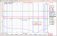
All testing done with an AIM-4170 uhf Network Analyzer and precision 125 ohm non inductive resistive load
Specifications
| Core Material | Custom mix low permeability ferrites by Fair Rite Products for maximum bandwidth. Cores are coated and sealed for long term durability. |
| Winding Type | Two separately wound large toroids. First is 1:1 balun at 125 ohms. Winding is 14 gauge Thermaleze wire inserted in teflon tubes to achieve the characteristic impedance of 125 ohms. Second core is trifilar wind of thermaleze wire creating a 2.5:1 Unun providing the impedance transformation from 125 ohms to 50 ohms unbalanced. |
| Winding Material | Essex heavy build polyamideimide Allex 240 Winding Wire Windings are inserted into Teflon tubes increasing total breakdown to >10,000 volts. |
| Power Rating | 1.5 to 54 MHz - 3kW continuous on specified bands. When used on WARC or bands out of design spec, power should limited to 1.5 kW ICAS High SWR will reduce power handling ability as discussed in description. |
| Useable Frequency | 1.5 to 45 MHz |
| Insertion Loss | Less than 0.05db |
| Connectors | SO-239 connectors are silver plated with Teflon insulation. Studs and eyebolts are 1/4 inch. Alternate connectors and Mounting Options are available in the Accessories section. |
| Hardware | All Stainless Steel |
| Enclosure Type |
NEMA rated 4x marine grade junction box for outdoor installations. Cover utilizes integral neoprene gasket for weatherproof integrity. |
| Dimensions | 4x4x2 inches for main body of unit Dimensional Drawing of Standard Enclosure |
| Additional Info | Very high efficiency |


