Description
After much research and testing, a new transformer design for End Fed Half Wave (EFHW) antennas has been achieved. Developed by Bob Glorioso, W1lS and Bob Rose KC1DSQ, they discovered that most transformers for EFHW antennas used higher impedance transformations than necessary and were wound in a way that limits the high frequency response of the transformer. By utilizing their capacitive loading technique developed for OCF antennas, they created an EFHW antenna with low SWR on all bands 80-10m. In addition to their capacitive loading, the "Bobs" also found the most important thing to make EFHW antennas work consistently on all bands was the need for a properly sized counterpoise as shown in the diagrams above.
For proper operation with this EFHW design, a quality 1:1 choke balun with a minimum of 30db suppression is essential to the overall performance. Depending on your decision for which counterpoise option you will use, the choke balun is installed either immediately behind the EFHW transformer or at the end of the coax length recommended for the use of your coax shield. An air wound coax choke (aka Ugly balun) and many commercial units are unable to provide adequate choking for proper operation of this unit.
The SWR plots shown are applicable ONLY when capacitive loading is used as described in the article referenced below.
Complete design and installation recommendations are available using the link below to view the authors' CQ article.
Please be sure to carefully follow the Installation Notes when installing the choke balun.
Installation Notes 
Specifications
| Core Material | Mid range permeability ferrite by Fair Rite Products for maximum bandwidth. |
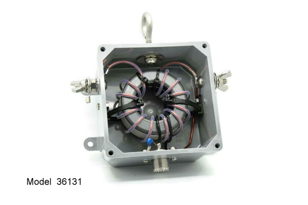
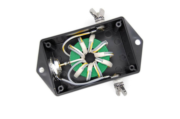
| Winding Type | Stacked cores with winding configured as 36:1 auto transformer Downward impedance transformation by factor of 36. |
| Winding Material | 14 gauge Superior Essex Heavy build polyamideimide Allex 240 Winding Wire. Windings are inserted into Teflon tubes increasing total breakdown to 10,000+ volts. |
| Power Rating | 3 to 31 MHz - up to 800 watts intermittent (50% duty cycle). See additional Information |
| Useable Frequency | 3 to 31 MHz |
| Insertion Loss |
0.3 to 0.65 db based on frequency |
| Connectors | SO-239 connectors are silver plated with Teflon insulation. Studs and eyebolts are 1/4 inch stainless steel. Alternate connectors and Mounting Options are available in the Accessories section. |
| Hardware | All Stainless Steel |
| Enclosure Type |
NEMA rated 4x marine grade junction box for outdoor installations. Cover utilizes integral neoprene gasket for weatherproof integrity. |
| Dimensions | 4x4x2 inches for main body of unit Dimensional Drawing of Standard Enclosure |


