
Effect of Stray Capacitance on Testing
We occasionally receive emails from customers who feel their balun is defective because they are unable to replicate our test results. This is due in large part to the effect of stray capacitance picked up by the testing method they use. For example, 3 pF of stray capacitance represents a reactance of about 1.7K ohm at 30MHz which will appear to be in parallel with the load. This will seriously affect readings at higher frequencies if the capacitance is not properly eliminated.
For Common-Mode chokes used in RF applications, stray test-fixture capacitance can resonate with the choke's inductance which can have a dramatic effect on the measured impedance. This becomes more and more noticeable at higher frequencies. What follows is a pictorial review of our testing procedure and the methods used to eliminate the effect of stray capacitance. For reference, we also show a scan using a non inductive 50 ohm resistor with wire leads and the magnitude of error this typical testing method introduces in to the results.
 Test Setup using Precision 50 ohm Load
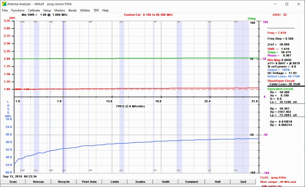 Figure 1
The scan in Figure 1 shows the results using an AIM 4170UHF network analyzer utilizing a precision encapsulated/shielded 50 Ohm load.
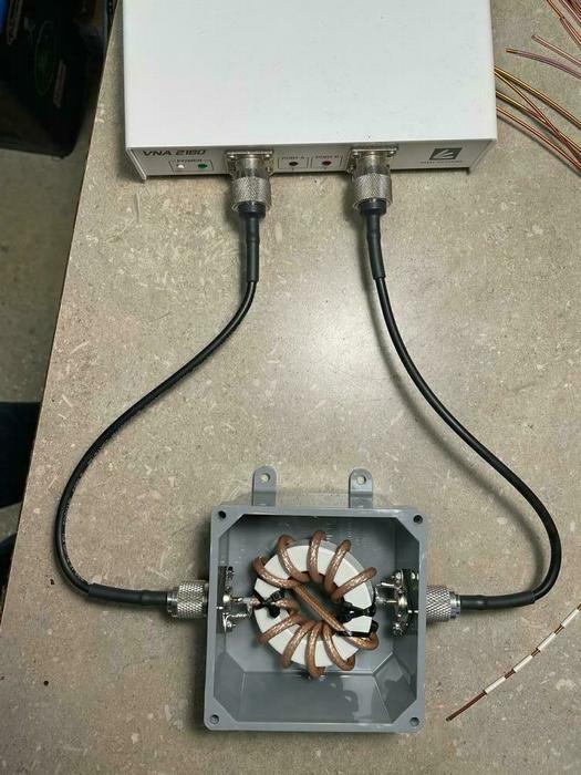
 Test setup utilizing a 50 ohm non inductive resistor w/ wire leads
 Figure 2
This is the same scan with the only difference being the 50 ohm load now has wire leads. Note the dramatic impact of stray capacitance picked up by the leads of the resistor. If the model being tested has studs on the sides or top, the longer wire leads required to connect the resistor will increase the capacitance pick up area further exacerbating the resulting impedance mismatch.
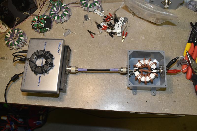
For those interested, here is the full layout of our test setup using the AIM 4170 and the VNA 2180. The VNA is used to measure insertion loss and suppression in db. We should also note the impact of this capacitance is the most noticeable on 1:1 baluns. The complex winding of other ratios can reduce or eliminate the effect of this capacitance on test results.
Recent Posts
-
In Defense of the 4:1 "Single Core" Balun
Recently a few of the less open minded purists in our hobby have begun a negative compaign focused o …1st Sep 2025 -
Baluns, Ununs and Power Ratings
Currently there is no industry standard for measurement of power ratings for baluns and ununs. Beca …2nd Aug 2024 -
All About the 1:1 Current/Choke Balun
How a 1:1 Guanella-Balun (Current-Balun) OperatesBy Jerry Sodus, KM3K In the spirit of the hobby, I …2nd Aug 2024